CAD Panel Schematics
Virtually everything that we build is based on either CAD drawings or schematics. They can be as varied as a single page, muliple pages or a plotted drawing.
Every drawing is specific to the project assigned to it. All inputs/outputs can be described based on the customers' requirements to allow for easier diagnosis and troubleshooting.
Depending on the complexity of your specific drawing and based on your panel design, a schedule of relay functionality can be included.
Generally, all schematics are in 11" x 17" format. For storage purposes, a PDF of all schematics is also created.
Some sample schematics are available below
Boiler Pump 1 Pump 2 Zone PLC + Pool
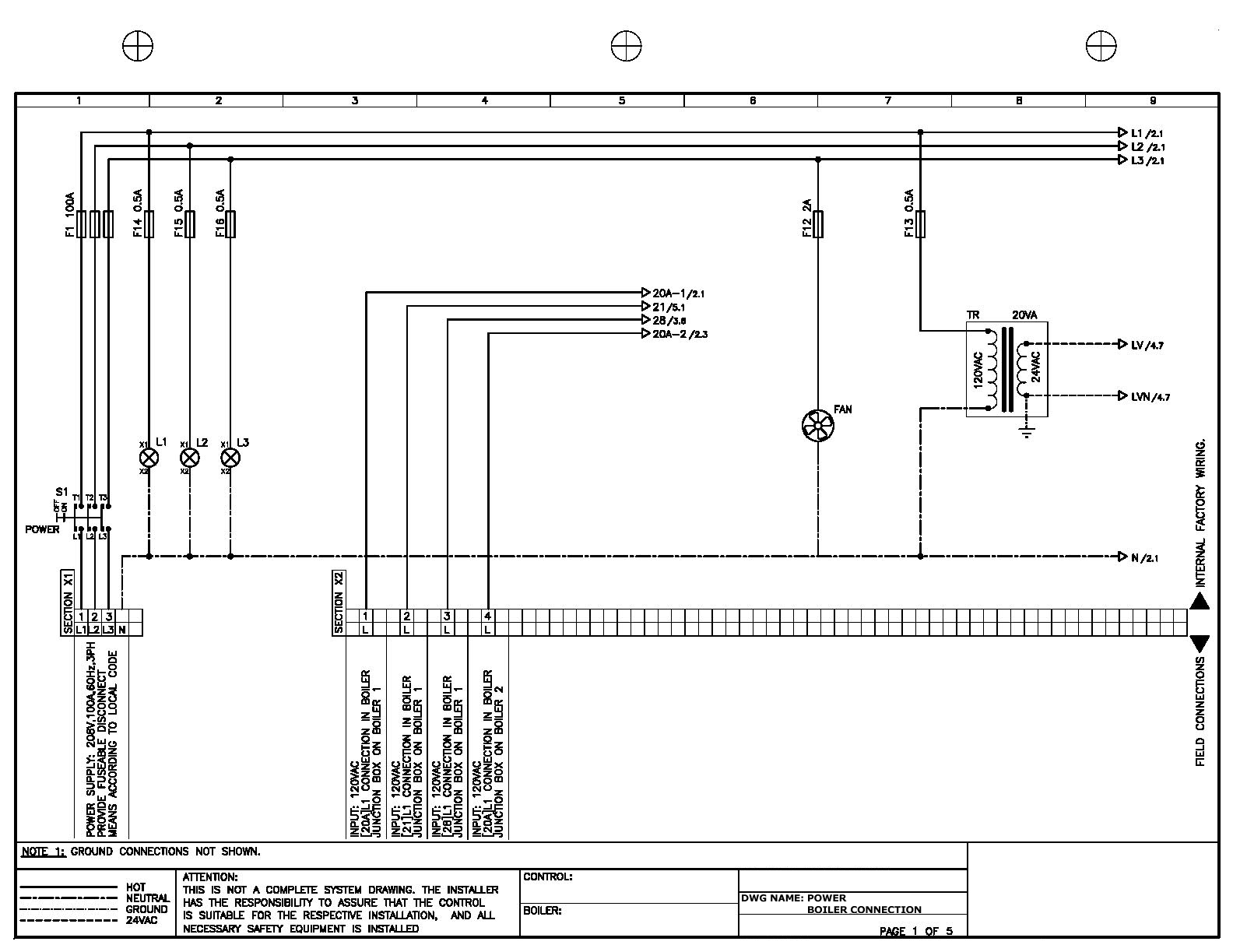
Power Boiler Connection
These schematics are for illustration purposes only. They are not to be used for anything other than what they were intended.
Click image to enlarge